CJ-3A, CJV-35/U, and M38 Fuel pump
information and rebuilding.
Description of operation
Helpful information
Testing
Removal and installation
Part numbers
Special tool for pump
rebuilding
CJ-3A, CJV-35/U pump rebuilding
M38 pump rebuilding
Modification of M38 Fuel Pump
Description
of operation
These mechanical fuel pumps are the diaphragm type, driven from an
eccentric on the engine camshaft. As the eccentric moves the rocker arm
the diaphragm is pulled against the pressure of the diaphragm spring. A
vacuum is formed in the fuel chamber and fuel is drawn in through the
inlet check valve(s) from the fuel tank. As the eccentric rotates the
pressure on the rocker arm is released and the diaphragm spring pushes
the diaphragm forcing fuel out to the carburetor through the outlet
check valve(s). When the carburetor does not require fuel, the pressure
in the fuel chamber holds the diaphragm and diaphragm spring in
compression and fuel does not flow. The fuel pump output pressure is
proportional to the force of the diaphragm spring.
The vacuum booster section of the fuel pump operates in the same
fashion as the fuel pump. Its purpose is to provide vacuum for
windshield wiper operation under higher throttle conditions where
engine manifold vacuum is too low for satisfactory wiper operation.
When engine manifold vacuum is greater than
that created by the pump, the stronger manifold vacuum pulls the
diaphragm into the air chamber against spring pressure and the pump
does not pump.
Helpful
information
The CJ-3A, CJV-35/U and M38 utilize spacers between the fuel
pump
and the engine block. Over the years these spacers are often removed
for various reasons. The CJ-2A style fuel pump is often retrofitted to
these vehicles due to its lower cost. This is a fuel pump only, without
the vacuum booster section. It does not require a spacer for proper
operation. Lack of a
spacer on the original CJ-3A, CJV-35/U and M38 fuel pumps can cause
excessive fuel pressure. Fuel pressure can be lowered slightly by
adding extra gaskets between the fuel pump and engine block.
Old stock pumps and rebuild kits. Diaphragms stretch and deteriorate
with age. Old diaphragms are not made to withstand
today's fuel compositions. It is best to use modern replacement
diaphragms.
Venting of the fuel pump. CJ-3A fuel pumps have a vent in the body of
the fuel pump, as most fuel pumps do. Since the CJV-35/U was designed
to operate underwater, the vent is eliminated as well as the upper oil
seal. M38s before serial number 53262 originally had a plug in the body
center threaded hole. This is where a vent would normally be located.
Apparently there were problems with this
arrangement since many vehicles were retrofitted with various vents
here. The service manual also has a modification procedure to be
performed on the pumps. M38s after serial number 53262 had a different
underwater ventilation system and the fuel pump was vented at the
center of the body. See M38
Underwater Ventilation System for more information.
Testing
Caution Gasoline and gasoline vapors are highly flammable. A fire could
occur if an ignition source is present. Have a dry chemical (Class B)
fire extinguisher nearby.
Fuel pump pressure test. Connect a fuel pressure gauge to the fuel
pump output line. Run the engine at a fast idle and note the pressure.
CJ3A and CJV-35/U fuel pressure should be 2-1/2 to 3-3/4psi and M38
fuel pressure should be 4 to 5-1/4 psi.
Fuel pump capacity test. Connect a hose to the fuel pump output and
place in a
container. Start the engine and run at idle speed. It should take 20-30
seconds to pump 1 pint of gasoline into the container.
Vacuum pump test. Disconnect the vacuum line going to the intake
manifold and plug the manifold side of the line or fitting. With the
engine
idling, if the windshield wipers operate even at a slow speed, the
vacuum pump is satisfactory. With the manifold line still disconnected,
attach a vacuum gauge to the line that goes to the wipers. Vacuum
should be about 10 in. of vacuum at a fast idle.
Problem and possible cause
Low fuel pressure - Mechanical wear, Stuck or leaking valves, Leaking
diaphragm,
Fuel
supply
problem,. Dirty filter screen, Suction side air leak
Low fuel volume - See low fuel pressure
High fuel pressure - Tight diaphragm, Diaphragm spring too strong,.
Frozen
link, Missing spacer, The 1956 Utility service manual states
"High fuel pressure
may be corrected by adding gaskets between the pump
body and engine block."
Fuel leak at center of fuel pump - Ruptured fuel diaphragm
Fuel in engine oil - Ruptured fuel diaphragm
Low vacuum - Ruptured vacuum diaphragm, Air
leak, Mechanical wear.
Slow wipers - Ruptured vacuum diaphragm, air
leak, Mechanical wear.
Rough idle - Ruptured vacuum diaphragm, air
leak
Oil consumption - Ruptured vacuum diaphragm
Removal
and installation
Caution Gasoline and gasoline vapors are highly flammable. A
fire could
occur if an ignition source is present. Have a dry chemical (Class B)
fire extinguisher nearby.
Remove fuel cap to relieve pressure. Disconnect the fuel and vacuum
lines from the pump. Plug the fuel supply line so gasoline will not
gravity drain from the tank. Remove the 2 bolts that attach the fuel
pump to the engine block. The M38 uses special bolts with and extended
hex section to allow
easier removal and installation of the fuel pump.
Clean the old gaskets from the pump, spacer and the block.
For easier installation of the fuel pump, rotate the engine crankshaft
until the fuel pump camshaft eccentric lobe is on the low point. Look
into the fuel pump opening to determine the low point. Alternately the
engine can be set at top dead center of cylinder number 1 compression
stroke so the lobe is at the low point. Pre-lubricate the fuel pump arm
where it will contact the camshaft. Place the bolts in the fuel pump
holes. Install 1 new gasket over the bolts. Install the spacer over the
bolts. Install the second gasket over the bolts. Insert the fuel pump
arm into the block being sure the arm goes on top of the camshaft
eccentric lobe. Start the bolts in the block threaded holes and evenly
tighten them. Connect the fuel and vacuum lines.
Part numbers
The fuel pump part number is usually
stamped on the edge of the mounting flange. Some high production pumps
have the part number cast into the body beneath the diaphragm flange.
CJ-3A
Pump WO-647911
Spacer WO-647669, approx. 1/8" thick
CJV-35/U
Pump WO-648379, AC-1539556
Spacer WO-647669, approx. 1/8" thick
M38
Pump AC-1539585, WO-800350, ORD-7375380 through engine #74419;
AC-1539917,
WO-807641, ORD-8330132 after engine #74419
Spacer WO-800361, ORD-8329708, approx. 1/2" thick
WO Willys part number
AC Manufacturers part number
ORD Military part number
The following information is copied
from
TM
9-1828A
Fuel Pumps
December 1952
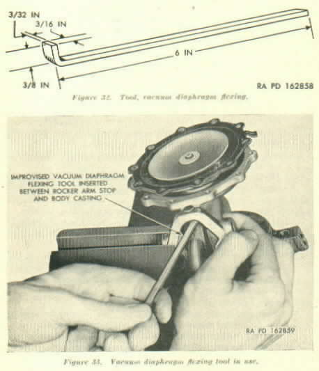
Special
Vacuum Diaphragm Tool
Figure 32 and figure 33, Special Tool
CJ-3A, CJV-35/U pump rebuilding
Section
XXVII. SERIES CF FUEL AND
VACUUM PUMPS
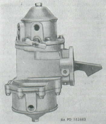
Figure 57. Fuel and vacuum pump,
series CF.
87. Disassembly (fig. 58)
a. Separate
Fuel Cover From Body.
(1) Mark edges of fuel cover and body diaphragm
flanges of series CF fuel and vacuum pump (fig. 57) with a file. Mark
heat shield stud if used. The parts then may be assembled in the same
relative position. Note that the fuel diaphragm flange is symmetrical
and the vacuum diaphragm flange has bulges where the screw holes occur.
(2) Remove cover screws and lock washers. Also remove
heat shield stud, if used. Separate cover from body by jarring cover
loose with a light plastic hammer.
b. Separate Vacuum Cover From Body.
(1) Mark edges of vacuum cover and body diaphragm
flanges. Mark at heat shield stud, if used. The parts may then be
assembled in the same relative position.
(2) Remove only two cover screws front opposite sides
of the cover and substitute for them two No. 10-32 x 1-1/2" fillister
head screws. Turn the two long screws all the way down then remove the
balance of the regular cover screws. Alternately back off the two long
screws, a few turns at a time, until the force of the heavy vacuum
diaphragm spring is no longer effective. Tap the cover with a light
plastic hammer if the flanges stick together. Remove the two long
screws, the cover assembly, diaphragm spring, and spring retainer.
c. Disassemble Body.
(1) File riveted end of rocker arm pin flush with
steel washer. Drive out the rocker arm pin with a drift punch and
hammer. Wiggle rocker arm until links unhook from both diaphragms.
Remove rocker arm spring, rocker arm, and link assembly.
(2) Remove bushing from rocker arm which disengages
two vacuum links, one fuel link, link spacer, and link washers.
(3) Lift vacuum diaphragm out of pump body. Lift fuel
diaphragm out of pump body and remove spring retainer and spring.
d. Disassemble Vacuum Cover.
(1) Remove two screws holding valve and cage
retainer. Lift out valve and cage retainer, two valve and cage
assemblies, and gasket.
(2) Remove bowl screw with gasket. Remove bowl, bowl
gasket and screen.
e. Disassemble Vacuum Cover.
(1) Remove valve and cage retainer screw. Lift out
retainer, two valve and cage assemblies, and two gaskets.
(2) Remove cover plate screw with gasket. Lift off
the cover, cover gasket, screen retainer, and screen.
88. Cleaning and
Inspection (CJV-35/U fuel pumps did not use an oil seal in the body on
the fuel side)
a. Clean All
Parts
(1) Clean all metal parts in dry-cleaning solvent or
volatile mineral spirits. Blow out all passages with compressed air. If
difficulty is experienced in cleaning parts, use
carbon remover solvent.
(2) Check fuel Pump number on edge of mounting flange
and select propel repair kit using table II. All parts in the standard
repair kit must be installed when a
fuel pump has been disassembled
for rebuild.
b. Inspection.. Make the following inspection
of fuel
pump parts which are not included in the repair kit:
(1) Top cover. Discard cover if cracked or broken, or
if the diaphragm flange is warped more than 0.010 inch. If warped less
than 0.010 inch, flatten with disk grinder. Discard
cover if bowl
gasket seat is warped more than 0.010 inch. Discard valve seat
insert-type covers when any part of raised valve seat is worn flush
with shoulder of valve. Stripped or crossed threads
can sometimes be
corrected with a thread chaser, or drilled out and retapped to a larger
size.
(2) Body. Discard body if diaphragm flange is warped
more than 0.010 inch. If warped less than 0.010 inch, refinish with
disk grinder. Discard cover if
threaded holes in diaphragm
flange are
stripped or crossed. Stripped or cross threads can sometimes be
corrected with a thread chaser, or drilled out and
retapped to a larger
size. Discard body if rocker arm stop is broken.
(3) Rocker arm. Discard only if obviously worn or
broken.
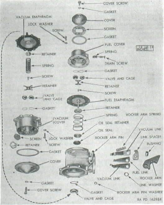
Figure 58 Fuel and vacuum
pump-disassembled view (typical series CF construction)
89. Assembly
a. Assemble Body (fig. 58).
(1) Assemble link spacer over fuel link. Place one
vacuum link out each side of the fuel link. The hook ends of the vacuum
links must come together so they surround the fuel link. All link hooks
should point in the same direction. Place assembly of links and spacer
between lobes of rocker arm with one spacer washer to the outer side of
each vacuum link. Slide rocker arm bushing through holes in rocker arm,
spacer washers, and links.
(2) Stand the pump body on the bench, fuel flange
down. Set rocker arm spring in position with one end over cone cast
into the body. Slide rocker arm and link assembly into body. Outer end
of rocker arm spring slips over projection on link spacer; the open end
of all link hooks must point toward vacuum flange. Align rocker arm
bushing hole with hole in body and retain assembly by driving rocker
arm pin through body and bushing. Place washer over small end of pin
and retain by spreading end of pin.
(3) Soak fuel diaphragm in clean kerosene. Fuel oil
may be used, but do not use shellac or sealing compound. Place spacer
in pull rod well of body casting. Set the diaphragm spring on the
spacer and the spring retainer on top of the spring, dish side down.
Hook diaphragm pull rod to center fuel link.
b. Assemble Fuel Cover.
(1) Place valve and cage gasket or two separate
gaskets in recesses provided. Place valve and cages on top of gaskets.
Inlet valve must have 3-legged spider facing out of cover; the outlet
valve must have 3-legged spider facing into cover. Secure valve and
cage assemblies with retainer and screw.
(2) Install strainer screen, cover gasket, cover,
cover screw gasket, and cover screw in the order named.
c. Assemble Fuel Cover to Body.
(1) Install cover on body, making sure that file
marks on cover and body line up. Push on rocker arm until diaphragm is
flat across body flange. Install cover screws and lock washers loosely
until screws just engage lock washers. Push rocker arm in full stroke
and tighten cover screws securely. Release rocker arm.
(2) Diaphragm must be held in flexed position while
tightening cover screws or pump will deliver too much pressure.
d. Assemble Vacuum Cover.
(1) Place two gaskets and two valve and cage
assemblies in cover. Inlet valve must have 3-legged spider facing out
of cover;
outlet valve must have 3-legged spider facing into cover. Secure valve
and cages with retainer and screw.
(2) Turn cover over, and set screen in recess over valve
hole. Set screen retainer on screen. Place cover gasket, cover, cover
screw gasket, and cover screw in position in the order named. Tighten
cover screw.
e . Assemble Vacuum Cover to
Body.
(1) Soak diaphragm in clean kerosene. Fuel oil may be used,
but do not use shellac or sealing compound.
(2) Lift the pump body above eye level, facing the vacuum diaphragm
flange. The two vacuum links will swing down so that the diaphragm pull
rod can be hooked to both links.
(3) While holding the vacuum diaphragm in position, the body should be
clamped in a vice, vacuum side up. Clamp on either side of the mounting
flange. The vacuum diaphragm must be held level with the body flange
during the following operations. The diaphragm is held level by
inserting a 3/32-inch piece of metal between rocker arm stop and body.
This tool can be made from a piece of steel, 3/16 x
3/32 x 6. Bend one end to form a right angle hook three-eighths of an
inch from bend to end (fig. 32).
(4) Place spring retainer on riveted end of diaphragm
pull rod and the spring on the retainer. Place vacuum cover over spring
and align the file marks.
(5) Insert two No. 10-32 x 1-1/2 screws in opposite
holes in cover flange. Turn these long screws down alternating a few
turns on each. Insert regular screws with lock washers and tighten
until screws just engage lock washers. Replace two lng screws with
regular screws and lock washers.
(6) Remove 3/32-inch tool from rocker arm position.
This allows the heavy vacuum spring to push diaphragm into flexed
position. Tighten all cover screws securely.
f. Test. Fuel and
vacuum pumps cannot be bench tested.
M38
pump rebuilding
Section
XXVIIL SERIES CU AND CY FUEL AND VACUUM PUMPS
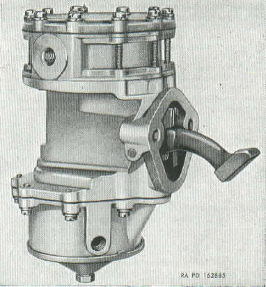
Figure 59. Fuel and vacuum pump-series CU and CV
90. Disassembly
(fig. 60)
a. Separate
Fuel Cover From Body.
(1) Mark edges of cover and body of series CU and CY
fuel and vacuum pump (fig. 59) with a file. The parts may then be
assembled in the same relative positions.
(2) Remove only the outer circle of screws (long) and
lock washers. Separate body from cover at diaphragm flange near body.
If cover sticks, it can be jarred loose with a light plastic hammer.
b. Separate Vacuum Cover From Body.
(1) Mark edges of vacuum cover and body diaphragm
flanges. Mark at heat shield stud, if used. The parts may then be
assembled in the same relative position.
(2) Remove only two cover screws from opposite sides
of the cover, and substitute for them two No. 10—32NF x 1½
filster-head screws. Turn the two long screws all the way down; then
remove the balance of the regular cover screws. Alternately back off
the two long screws, a few turns at a time, until the force of the
heavy
vacuum diaphragm spring is no longer effective. Tap the cover with a
light plastic hammer, if the flanges stick together. Remove the two
long screws, the cover assembly, diaphragm spring, and spring retainer.
c. Disassemble the Body.
(1) File riveted end of rocker arm pin flush with
steel washer, or cut off end with 3/8-inch drill. Drive out rocker arm
pin with a drift punch hammer. Wiggle rocker arm until links unhook
from both diaphragms. Remove rocker arm spring, rocker arm, and link
assembly.
(2) Remove bushing from rocker arm to disassemble
rocker arm, two vacuum links, one fuel link, link spacer, and link
washers (there may be one or two link washers).
(3) Lift vacuum diaphragm out of body. Remove fuel
diaphragm by pulling straight out.
(4) The diaphragm pull rod seals must be removed if
they exhibit wear or the sealing surfaces are torn. To disassemble
seals, it is necessary to remove metal displaced by staking operation.
Use a small chisel, round file or small grinding wheel. Pull seals out
of body with hook-shaped tool, being careful not to damage seal seats.
(5) Push the staked-in valve off its seat with a thin
rod or pencil. If the valve sticks to its seat under very light
pressure, if it moves downward and does not rebound, or if the cage is
damaged, the complete valve must be replaced. Remove staking with half
round file and pull valve out with hook-shaped tool.
d. Disassemble Fuel Cover. Remove two cover
center screws and lock washers. Lift off the pulsator cover plate and
three layers of pulsator diaphragm. Remove four screws from each of two
valve and cage retainers. Remove two retainers, six valve and cage
assemblies, and six gaskets.
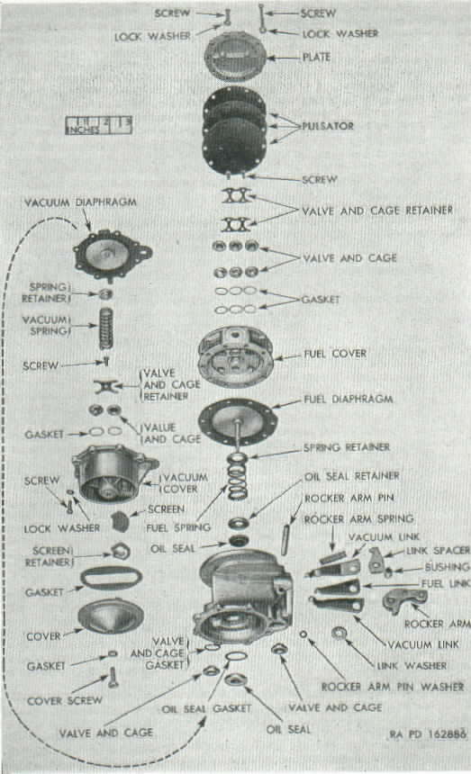
Figure 60. Fuel and vacuum pump,
disassembled view (typical series CU and CY construction).
91. Cleaning and
Inspection (Please see Modification
of M38 Fuel Pump below for updating your fuel pump)
a. Clean All
Parts
(1) Clean all metal parts in dry-cleaning solvent or
volatile mineral spirits. Blow out all passages with compressed air. If
difficulty is experienced in cleaning parts, use
carbon remover solvent.
(2) Check fuel Pump number on edge of mounting flange
and select propel repair kit using table II. All parts in the standard
repair kit must be installed when a
fuel pump has been disassembled
for rebuild.
b. Inspection.. Make the following inspection
of fuel
pump parts which are not included in the repair kit:
(1) Top cover. Discard cover if cracked or broken, or
if the diaphragm flange is warped more than 0.010 inch. If warped less
than 0.010 inch, flatten with disk grinder. Discard
cover if bowl
gasket seat is warped more than 0.010 inch. Discard valve seat
insert-type covers when any part of raised valve seat is worn flush
with shoulder of valve. Stripped or crossed threads
can sometimes be
corrected with a thread chaser, or drilled out and retapped to a larger
size.
(2) Body. Discard body if diaphragm flange is warped
more than 0.010 inch. If warped less than 0.010 inch, refinish with
disk grinder. Discard cover if
threaded holes in diaphragm
flange are
stripped or crossed. Stripped or cross threads can sometimes be
corrected with a thread chaser, or drilled out and
retapped to a larger
size. Discard body if rocker arm stop is broken.
(3) Rocker arm. Discard only if obviously worn or
broken.
92. Assembly
a. Assemble
Body (fig. 60).
(1) Place fuel section seal in recess of body with
large dished portion of seal down. Press retainer down firmly with flat
end of 7/8-inch diameter round bar. Retain by staking die cast lip in
four places.
(2) Place gasket in recess for vacuum section pull
rod seal and follow with seal, narrow diameter first. Press down firmly
with flat end of 7/8-inch diameter round bar. Retain by staking die
cast lip in four places.
(3) Place neoprene gasket in vacuum section valve
recess next to oil seal and follow with valve and cage, spring and cage
down. Firmly press valve and cage against neoprene gasket and retain by
staking die cast in three places around valve.
(4) Assemble link spacer over fuel link. Place one
vacuum link on each side of fuel link. The hook ends of vacuum links
should come together so they surround the fuel link. All link hooks
should point in the same direction. Place assembly of links and spacer
between lobes of rocker arm with one spacer washer on the outer side of
each vacuum link. Slide rocker arm bushing through holes in rocker arm,
spacer washers, and links.
(5) Place pump body on bench, fuel flange down. Set
rocker arm spring in position with one end over cone cast into body.
Slide rocker arm and link assembly into body. Outer end of rocker arm
spring fits over projection on link spacer. The open end of all link
hooks must point toward vacuum diaphragm flange. Temporarily retain
rocker arm and link assembly with a 4- or 5-inch length of 1/8-inch rod.
(6) Soak diaphragm in clean kerosene. Fuel oil may be
used, but do not use shellac or sealing compound. Turn pump body over
so fuel diaphragm flange is up. Set the diaphragm spring on the
staked-in seal and the retainer on top of the spring. Push diaphragm
pull rod through retainer. spring, and oil seal. Flat of pull rod must
be at right angles to fuel, link. Hook diaphragm pull rod to short,
center, fuel link.
(7) Drive temporary pin out with permanent pin. Place
washer over small end of pin and spread pin end to retain washer.
b. Assemble Fuel Cover. Place six valve and
cage gaskets in cover with six valve and cage assemblies on top of
gaskets. Inlet valve and cages must have 3-legged spider facing into
cover; outlet valve must have 3-legged spider facing out of cover.
Retain each set of three valve and cage assemblies with one retainer
and four screws. Place three layers of pulsator diaphragm on cover, and
follow with pulsator cover plate. Aline two center screw holes, and
insert two screws with lock washers through cover plate, pulsator
diaphragm, and into pump cover. Tighten screws securely.
c. Assemble Fuel Cover to Body.
(1) Install cover on body, making sure that file
marks on cover and body line up. Push on rocker arm until diaphragm is
flat across body flange. Install cover screws and lock washers loosely
until screws just engage lock washers. Push rocker arm in full stroke
and tighten cover screws securely. Release rocker arm.
(2) Diaphragm must be held in flexed position while
tightening cover screws, or pump will deliver too much pressure.
d. Assemble Vacuum Cover.
(1) Place two valve and cage gaskets in recesses
provided and follow with two valve and cage assemblies. Secure valve
and cages with retainer and screw.
(2) Turn cover over and set screen in recess over
inlet valve hole. Set retainer on screen. Place cover gasket, cover,
cover screw gasket, and cover screw in position in the order named.
Tighten cover screw.
e. Assemble Vacuum Cover to Body.
(1) Soak diaphragm in clean kerosene. Fuel oil may be
used, but do not use shellac or sealing compound. Push diaphragm pull
rod through oil seal with flat of pull rod at right angles to double
vacuum links.
(2) Clamp flange of pump in vise with vacuum section
up. Place 12-inch section of pipe over rocker arm and rise vacuum links
by moving rocker arm. Tilt diaphragm pull rod away from links, and as
links are raised, bring pull rod back to vertical. Repeat until pull
rod is securely hooked to both links.
(3) The vacuum flange must be held level with the
body flange during the following operations. The diaphragm is held
level by inserting a 3/32-inch piece of metal between rocker arm stop
and body. This tool (figs. 32 and 33) can be made from a piece of
steel, 3/16 x 3/32 x 6. Bend one end to form a right angle hook
three-eighths of an inch from bend to end (fig. 32).
(4) Lift diaphragm cloth and position valve and cage
in recess close to mounting flange. No gasket is required because the
diaphragm seals this valve cage.
(5) Place spring retainer on riveted end of diaphragm
pull rod and place the diaphragm spring on the retainer. Place vacuum
cover over spring and align file marks.
(6) Insert two 10-32NF x 1½ screws in opposite
holes in cover flange. Turn these long screws down, alternating a few
turns on each screw. Insert regular screws and lock washers and tighten
until screws just engage lock washers. Replace two long screws with
regular screws and lock washers.
(7) Remove 3/32-inch tool from rocker arm position.
This allows the heavy vacuum spring to push diaphragm to flexing stop
in body. Tighten all cover screws securely.
f. Test. Fuel and vacuum pumps cannot be
bench-tested.
Modification
of M38 Fuel Pump
From TM 9-8012, Jan 1956
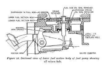
b. Modification of Fuel Pump (fig. 48). To minimize premature failures
of fuel pumps caused by excessive pressures within the fuel pump and
the trapped oil in the lower section of the upper body, modify the pump
as described in (1) through (8) below.
(1) Remove machine screw and lockwashers which secure the flanges of
the
upper and lower section bodies.
Note. Scribe marks on outer edge of flanges for alignment during
assembly.
(2) Remove upper fuel section body, diaphragm with pull rod, spring
retainer, and diaphragm spring.
(3) Using a hook-shaped tool, remove oil seal retainer and oil seal.
Exercise care during this operation to prevent damage to oil seal
retainer.
Note. If oil seal retainer is staked in place, remove the staking with
a small chisel, round file, or grinding wheel before pulling the
retainer and oil seal from the pump.
Discard the oil seal but retain the oil seal retainer if fuel pump
repair kit G740-73’75384 is used. Discard the oil seal and retainer if
fuel pump repair kit G758-8329981 is used.
(4) Drill a l/8-inch hole in deck of body (fig. 48) to act as an oil
return and pressure relief hole. Metal clips resulting from the
drilling should be blown from the fuel pump with compressed air.
(5) Install new oil seal and original retainer when using fuel pump
repair kit G740-7375384; if fuel pump repair kit G758-8329981 is used,
install oil seal retainer G758-8329706.
(6) Install diaphragm spring and spring retainer.
(7) Install new diaphragm with pull rod after soaking it in clean
kerosene. While holding the diaphragm flange in the upward position,
insert the pull rod through the
spring retainer, spring, and oil seal retainer in the lower fuel
section body. The flat of the pull rod must be at right angles to the
fuel link. Hook the pull rod to the
short (outer) fuel link.
(8) Aline the upper fuel section body on the lower fuel section body in
accordance with marks scribed in (1) above. Push on rocker arm until
diaphragm is flat across body flange. Install original screws and
lockwashers until screws just engage lockwashers. Push rocker arm in a
full stroke and tighten screws securely. Note. Diaphragm must be in
fixed (down) position while tightening cover screws, or pump will
deliver too much pressure.