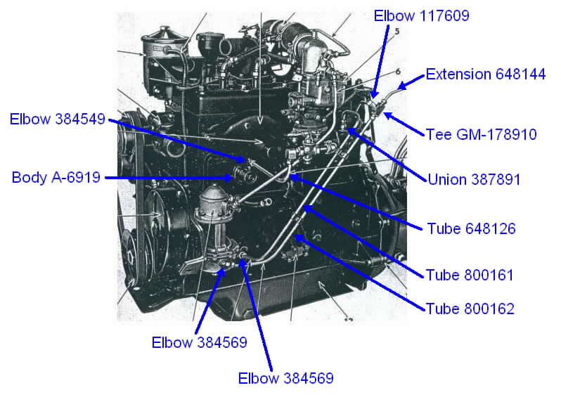
| A-6919 |
BODY, ventilator |
1 |
0107-N |
|
1 |
on side cover |
| A-6885 |
ELBOW, 5/16” inverted flared tube (WH-100-43405) |
1 |
0107-N |
|
1 |
Ventilation tube to control valve |
| 384549 |
ELBOW, 5/16” inverted flared tube (GM-137422) |
1 |
0107-N |
|
1 |
Ventilator to vent tube |
| 52805 |
ELBOW, 1/4-90*, inverted flared tube (GM-144112) |
1 |
0107-N |
1/4 street el |
1 |
Control valve to vent valve |
| GM 144592 |
NIPPLE, 1/4 x 1-3/8“ (Steel) (Interchangeable with GM-115144) |
1 |
0107-N |
1/4 pipe |
1 |
Control valve to vent valve |
| GM 115144 |
NIPPLE, 1/4 x 1-3/8“ (Brass) (Interchangeable with GM-144592) |
1 |
0107-N |
|
1 |
Control valve to vent valve |
| A-17842 |
PIN, swivel, ventilator valve |
1 |
0107-N |
|
1 |
part of 648083? |
| 53890 |
*SCREW, rd. hd., No. 6-32 x 3/16 |
1 |
0107-N |
|
1 |
|
| 53843 |
*WASHER, plain, 1/4 |
1 |
0107-N |
|
1 |
|
| 53891 |
*PIN, cotter, 1/16 x 7/16 |
1 |
0107-N |
|
1 |
|
| 648126 |
TUBE, crankcase ventilation, assembly |
1 |
0107-N |
|
1 |
|
| A-17841 |
VALVE, control, crankcase ventilation |
1 |
0107-N |
|
1 |
part of 648083? |
| 648083 |
VALVE, control, crankcase ventilation, assembly |
1 |
0107-N |
|
1 |
|
| A-6895 |
VALVE, ventilator, assembly (AC-1543018) |
1 |
0107-N |
|
1 |
pcv valve |
| 647551 |
FLANGE, pipe |
1 |
0300 |
1/8 pipe |
6 |
fuel tank vent fitting, top of tank |
| 53892 |
ELBOW, inverted flared tube, 5/16 |
1 |
0301 |
|
3 |
carb to vent tube fitting |
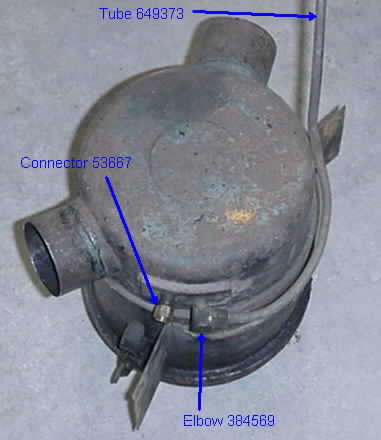
| 384569 |
ELBOW, 3/16, inverted flared tube |
1 |
0301-C |
90* 1/4 tube x 1/8 pipe |
5 |
air filter to wiper vent tube |
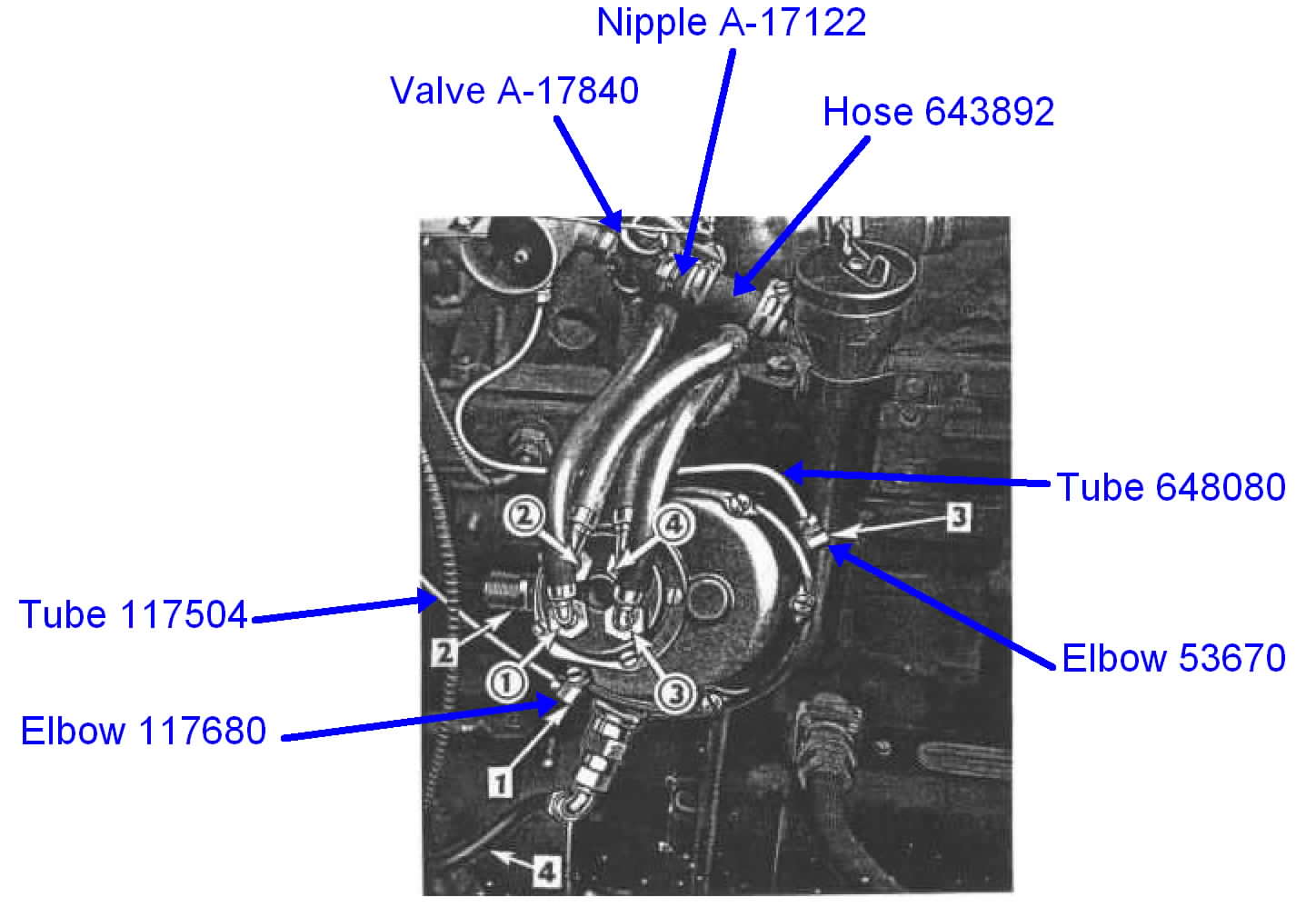
| 643892 |
HOSE, air cleaner tube to oil filler tube |
1 |
0301-C |
|
1 |
ok |
| 800780 |
HOSE, flexible, 2-1/8x5-1/2 |
1 |
0301-C |
|
intake
|
air filter to crossover |
| 801051 |
HOSE, flexible, 2-5/16x5-1/2 |
1 |
0301-C |
|
intake
|
crossover to carb |
| 649373 |
TUBE, assembly |
1 |
0301-C |
1/4 steel |
5 |
air filter to wiper vent hose |
| 117504 |
TUBE, vent, timer to intake manifold, assy |
1 |
0301-C |
|
4 |
ok |
| 800566 |
TUBE, w/bracket and valve, assy |
1 |
0301-C |
|
intake
|
air crossover pipe with control valve |
| A-17161 |
BRACKET, air intake pipe (Up to Serial No. . .) |
1 |
0301-D |
|
intake |
requires 2 spacers 800860, using up early inventory? |
| 54059 |
*BOLT, hex. hd., 5/16x24 x 1” (Up to Serial No..) |
2 |
0301-D |
|
intake |
|
| 52626 |
*NUT, hex.,5/16-24 |
2 |
0301-D |
|
intake |
|
| GM 446363 |
*WASHER, plain, 5/I6” (Up to Serial No..) |
2 |
0301-D |
|
intake |
|
| 52558 |
*WASHER, lock, 5/16 |
2 |
0301-D |
|
intake |
|
| A-17844 |
BRACKET, clamp, valve control conduit |
1 |
0301-D |
|
1 |
To crankcase ventilation valve, mounted on PCV valve
|
| A-17845 |
BRACKET, support, dual control |
1 |
0301-D |
|
1 |
To hood hinge bolt |
| 800893 |
BRACKET, air intake pipe (After Serial No..) |
1 |
0301-D |
|
intake |
no spacers required |
| 53068 |
*BOLT, hex. hd., 5/16x24 x3/4” (After Serial No..) |
2 |
0301-D |
|
intake |
Air intake bracket to RF fender |
| 52626 |
*NUT, hex.,5/16-24 |
2 |
0301-D |
|
intake |
Air intake bracket to RF fender |
| 53735 |
*WASHER, plain, 5/I6” (After Serial No..) |
2 |
0301-D |
|
intake |
Air intake bracket to RF fender |
| 52558 |
*WASHER, lock, 5/16 |
2 |
0301-D |
|
intake |
Air intake bracket to RF fender |
| 11386 |
CLAMP, (Bowden Wire) dual valve control |
2 |
0301-D |
|
1 |
on each cable bracket |
| 53889 |
*SCREW, rd. hd., No. 10-24 x 1-1/4 |
1 |
0301-D |
|
1 |
Dual control Bowden Wire to support bracket and clamp |
| 52237 |
*SCREW, rd. hd., No. 10-24 x1/2 |
1 |
0301-D |
|
1 |
Dual control Bowden Wire to support bracket and clamp |
| 53888 |
*NUT, sq., No. 10-24 |
4 |
0301-D |
|
1 |
Dual control Bowden Wire to support bracket and clamp |
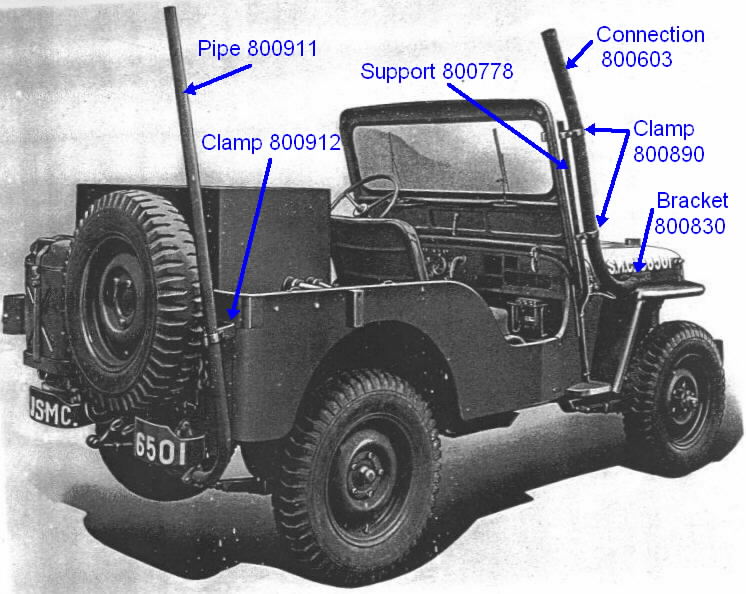
| 800890 |
CLAMP, flexible pipe to support tube |
4 |
0301-D |
|
intake |
|
| 635097 |
CLAMP, hose, 2-9/32” I. D. (USL-461389) |
1 |
0301-D |
|
intake |
Air intake hose to air cleaner |
| 800830 |
CLAMP, support, air intake flexible hose |
1 |
0301-D |
|
intake |
|
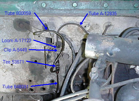
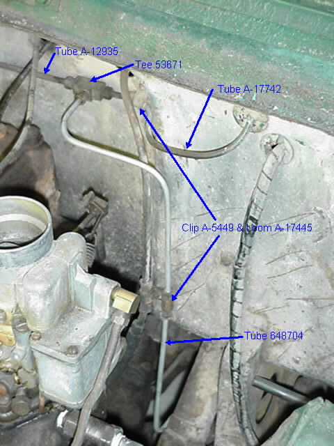
| A-5449 |
CLIP, 5/16 |
2 |
0301-D |
|
6,7
|
|
| 52868 |
*SCREW, rd. hd., No. 10-24 x 3/4 |
2 |
0301-D |
|
6,7 |
Tee to tee vent tube assembly to dash |
| 52651 |
*NUT, hex., No. 10-24 |
2 |
0301-D |
|
6,7 |
Tee to tee vent tube assembly to dash |
| 53762 |
*WASHER, plain, No.10 |
2 |
0301-D |
|
6,7 |
Tee to tee vent tube assembly to dash |
| 53381 |
*WASHER, lock, No. 10 |
2 |
0301-D |
|
6,7 |
Tee to tee vent tube assembly to dash |
| A-5449 |
CLIP, 5/16” |
1 |
0301-D |
|
7 |
Mounted to oil gage tube clip screw |
| A-5449 |
CLIP, 5/16”, ventilation tube to dash |
1 |
0301-D |
|
6
|
|
| 52868 |
*SCREW, rd. hd., No. 10-24 x 3/4 |
1 |
0301-D |
|
6
|
|
| 800603 |
CONNECTION, flexible, air tube, 74” long |
1 |
0301-D |
|
intake |
Air intake to air cleaner |
| 53667 |
CONNECTOR, 5/16, flared tube (GM-137404) |
1 |
0301-D |
straight 3/16 tube x 1/8 pipe |
2,6,7
|
Air cleaner to air cleaner vent tube |
| 53667 |
CONNECTOR, 5/16, flared tube (GM-137404) |
1 |
0301-D |
straight 3/16 tube x 1/8 pipe |
7 |
Master cylinder to master cylinder vent tube |
| 800921 |
CONTROL, dual, crankcase ventilating valve, assembly |
1 |
0301-D |
|
1 |
Air cleaner and crankcase ventilation vent valve |
| 801085 |
*NUT, special |
1 |
0301-D |
|
1 |
Mounting dual conrol |
| 801084 |
*WASHER, special |
1 |
0301-D |
|
1 |
Mounting dual conrol |
| 53670 |
ELBOW, 3/16, inverted flared tube, 1/8 pipe |
1 |
0301-D |
90* brass |
6 |
Fuel tank to fuel tank vent tube |
| 53670 |
ELBOW, 3/16, inverted flared tube, 1/8 pipe |
1 |
0301-D |
90* brass |
4 |
Timer to air cleaner vent tube to timer |
| 53670 |
ELBOW, 3/16, inverted flared tube |
1 |
0301-D |
90* brass |
2 |
Transfer case vent to vent tube |
| 53892 |
ELBOW, 5/16” x 1/8-90*, flared, ventilating tube (GM-111284) |
1 |
0301-D |
|
3 |
?carb vent ?? |
| A-17444 |
LOOM, 30” long |
1 |
0301-D |
|
6 |
on fuel vent tube inside cab |
| A-17445 |
LOOM, split, 3/16 x 1” |
1 |
0301-D |
|
7 |
Master cylinder vent tube to dash |
| A-17445 |
LOOM, 3/16” x 1”, split |
2 |
0301-D |
|
6,7
|
Tee to tee vent tube assembly to dash |
| A-17122 |
NIPPLE, 1/4”, pipe |
1 |
0301-D |
|
1 |
For vent valve hose connection |
| 53668 |
NUT, 3/16”, flared tube |
12 |
0301-D |
|
all
|
flare nuts, part of all the tubes |
| 384526 |
NUT, ventilating tube (5/16” flared) |
2 |
0301-D |
|
3 |
part of tube 648126 |
| A-17842 |
PIN, swivel, ventilator valve |
1 |
0301-D |
|
1 |
|
| 53890 |
*SCREW, rd. hd., No. 6-32 x 3/16 |
1 |
0301-D |
|
1 |
Valve shut-off control connection |
| 53843 |
*WASHER, plain, 1/4 |
1 |
0301-D |
|
1 |
Valve shut-off control connection |
| 53891 |
*PIN, cotter, 1/16 x 7/16 |
1 |
0301-D |
|
1 |
Valve shut-off control connection |
| 648452 |
RING, anti-rattle, air intake tube |
1 |
0301-D |
|
intake
|
|
| 800860 |
SPACER, air intake pipe bracket (Up to Serial No. . ) |
2 |
0301-D |
|
intake
|
|
| A-17380 |
SPACER, flexible pipe to support tube clamp, 5/16 I. D. x
5/8” long |
2 |
0301-D |
|
intake
|
|
| 53751 |
*SCREW, rd. hd., 1/4-20 x 1-1/2 |
2 |
0301-D |
|
intake |
Air intake flexible pipe to support tube |
| 53741 |
*NUT, wing, 1/4-20 |
2 |
0301-D |
|
intake |
Air intake flexible pipe to support tube |
| 53340 |
*WASHER, lock, 1/4, internal |
2 |
0301-D |
|
intake |
Air intake flexible pipe to support tube |
| 800778 |
SUPPORT, carburetor air intake tube |
1 |
0301-D |
|
intake |
|
| 53931 |
*BOLT, hex. hd., 5/16-18 x 7/8 |
2 |
0301-D |
|
intake |
Support and clamp to cowl side |
| 52558 |
*WASHER, lock, 5/16 |
2 |
0301-D |
|
intake |
Support and clamp to cowl side |
| 53671 |
TEE, 3/16”, flared tube |
1 |
0301-D |
brass |
6,7
|
Tee to tee vent tube, master cylinder and fuel tank vent
tube. left dash tee |
| 53671 |
TEE, 3/16”, flared tube |
1 |
0301-D |
brass |
2,6,7
|
Transfer case vent tube, air cleaner vent tube and tee to tee
vent tube. right dash tee |
| A-17742 |
TUBE, fuel tank vent to tee, assembly |
1 |
0301-D |
3/16 copper |
6 |
54-1/4” long |
| 648081 |
TUBE, transfer case vent to tee, assembly |
1 |
0301-D |
3/16 steel |
2 |
|
| 800059 |
TUBE, vent, air cleaner to dash tee, assembly |
1 |
0301-D |
3/16 steel |
2,6,7 |
|
| A-12935 |
TUBE, vent, assembly, 17-1/2” long |
1 |
0301-D |
3/16 steel |
6,7
|
Tee to tee on dash |
| A-17866 |
TUBE, ventilating, carburetor, assembly |
1 |
0301-D |
5/16 |
3 |
Carburetor to housing tube |
| 648080 |
TUBE, ventilation, assembly |
1 |
0301-D |
3/16 steel |
4 |
Timer to air cleaner tube |
| 648704 |
TUBE, ventilation, master cylinder to tee, assembly |
1 |
0301-D |
3/16 steel |
7 |
23” long |
| A-17840 |
VALVE, ventilation, air cleaner tube, assembly |
1 |
0301-D |
|
1 |
|
| A-17082 |
VENT, transfer case |
1 |
0301-D |
|
2 |
pipe bushing? |
| 384569 |
ELBOW, connector, 1/4 flared tube |
3 |
0302-A |
1/4 tube x 1/8 pipe |
5 |
2 vacuum tube connectors at pump, 1 for fuel |
| A-1694 |
CLIP |
|
0304 |
|
5 |
illustration p50 shows 4 clips holding vacuum tubes together |
| 800161 |
TUBE, vacuum, intake manifold to pump |
1 |
0304 |
1/4 tube |
5 |
|
| 387891 |
UNION, 1/4, inverted flared tube (interchangeable with
GM-145474) |
1 |
0304 |
1/4 tube x 1/8 pipe |
5 |
Vacuum tube to manifold |
| GM-145474 |
UNION, 1/4, inverted flared tube (interchangeable with 387891) |
1 |
0304 |
|
5 |
Vacuum tube to manifold |
| 800911 |
PIPE, tail, exhaust, assembly |
1 |
0401 |
|
exhaust
|
exhaust pipe snorkle |
| 800912 |
CLAMP, exhaust tail pipe to body, assembly |
1 |
0401 |
|
exhaust |
exhaust pipe snorkle to body bracket |
| 117608 |
ELBOW, 90*, inverted flared tube |
1 |
0603 |
|
4 |
?vac tube at dist? |
| 117609 |
ELBOW, 90*, flared type, .042 orfice |
1 |
0603 |
90* 3/16 tube x 1/8 pipe |
4 |
distributor vacuum restriction at wiper tee |
| 648144 |
EXTENSION, windshield wiper tube, assembly |
1 |
1811-D-1 |
1/4 tube |
5 |
Tube extension to tee |
| GM-178910 |
TEE, inverted flared tube, 1/4x1/4x1/8 pipe |
1 |
1811-D-1 |
1/8 street tee, 3750x2 |
5 |
Windshield wiper tube, extension and distributor vent tube.
wiper tee |
| 800162 |
TUBE, windshield wiper, assembly |
1 |
1811-D-1 |
1/4 tube |
5 |
Vacuum pump to tee |