Home | Site Map | Contact Information
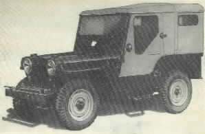
Civilian Jeep Engine
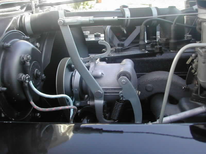
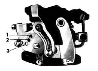
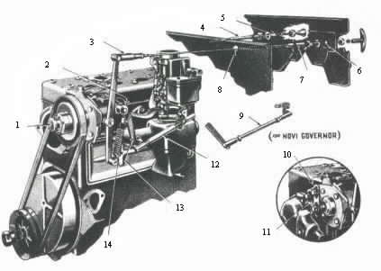
Speed Governors
A governor operates like a cruise control; the engine speed is
maintained at a preset value regardless of the load applied. They are
commonly
utilized while running PTO driven equipment. The
controlled
engine speed is set with the hand control mounted on the dash.
With this control at the first notch the controlled engine speed is
1000 rpm. The speed is increased 200 rpm per notch, as the hand
control is pulled out. The top speed is 2600 rpm at the 9th notch. The
hand control is released by turning the handle ¼ turn in either
direction. Three different governors are used as standard in
production: the Novi,
the King Seeley
and the Monarch. Other types of governors were used on stationary
equipment, such as generators and compressors. See the photos below to
help identify each governor
type.
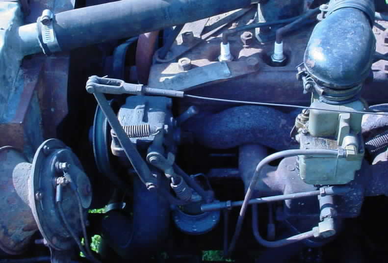
Novi
Governor on a 1948 CJ-2A
Art Contoni photo
The CJ-3A Story | CJ-3A
Photos | CJ-3A Specs and Tech Tips | CJ-3A Literature | Siblings of the CJ-3A | Accessories | Links
cj3a 10/06